














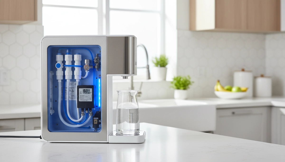
The Hardware Ecosystem: Components Controlled by Logic
The efficacy of Pressure Regulation Logic in Countertop RO Dispensers is strictly defined by the caliber of the electromechanical components interfacing with the central PCB. Unlike under-sink systems relying on line pressure, standalone units like Driplife utilize a closed-loop internal ecosystem where the controller must actively generate and manage hydraulic force.
The Diaphragm Booster Pump: VFD vs. Standard DC
The heart of the pressure generation system is the pump. While entry-level units utilize standard DC pumps operating on a binary On/Off basis, advanced pressure regulation ro dispenser designs incorporate Diaphragm Pump PWM Control.
- Standard DC Pumps: Operate at a fixed RPM, leading to sharp pressure spikes and increased wear on the 0.0001-micron RO membrane.
- Variable Frequency Drive (VFD) Logic: Utilizing Pulse Width Modulation (PWM), the logic board adjusts the duty cycle of the pump. This allows for soft starts to mitigate hydraulic shock and enables Variable Frequency Pump Logic to maintain constant membrane pressure even as the feed water level in the raw tank decreases.
Transducers vs. Switches: Granular Control Architecture
Precision logic requires precise data. The transition from mechanical switches to electronic sensors marks the difference between basic safety and intelligent operation.
- Binary Switches (HPS/LPS): Traditional High-Pressure Switches (HPS) and Low-Pressure Switches (LPS) provide simple open/closed signals. They can only tell the system if pressure is “enough” or “not enough,” resulting in frequent short-cycling.
- Pressure Transducers: Modern logic utilizes Feed Water Pressure Transducers that send real-time voltage signals to the PCB Control Loop. This allows the processor to read exact PSI values, enabling the system to modulate pump speed dynamically rather than triggering an abrupt shutdown.
Solenoid Valves: Precision Flow Actuation
Solenoid Valve Actuation serves as the physical execution of the logic board’s commands, directing fluid dynamics within the manifold.
- Inlet Solenoid: Governs the entry of water from the raw tank to the filtration array. Logic ensures this valve opens only after the pump initializes, preventing airlocks.
- Waste Solenoid & Flow Restrictors: Essential for the Countertop RO Flow Restrictor mechanism. The logic board toggles the waste solenoid to manage the brine discharge ratio, ensuring the membrane pressure optimization remains within the safe operating window while maximizing water efficiency.
The Core Logic Cycle: From Startup to Standby
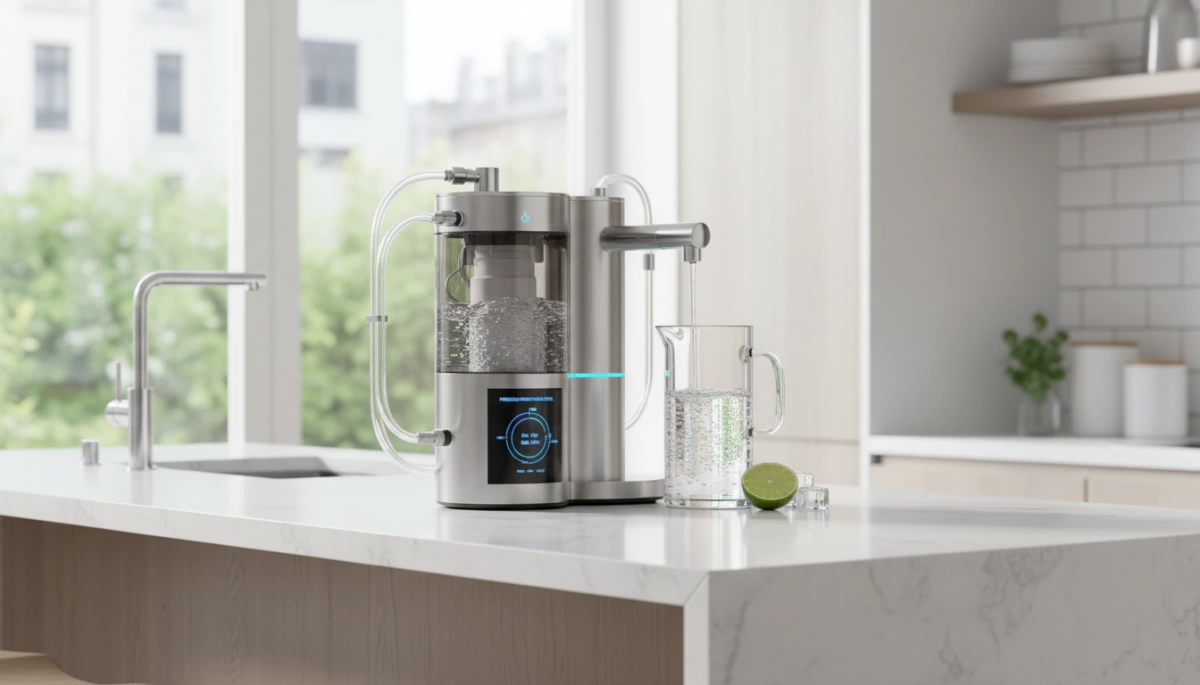
At Driplife, we design our systems to think before they act. The filtration process isn’t just about pushing water through a filter; it is a carefully choreographed sequence managed by our internal ro pump logic. This ensures that every drop of water meets our strict purity standards without stressing the mechanical components.
Phase 1: Source Verification (Low-Pressure Logic)
Before the pump ever engages, the system performs a critical diagnostic check. We utilize a Dry-Run Protection Sensor to verify the presence of water in the raw tank. If the sensor detects a low water level, the logic board intervenes immediately, preventing the pump from starting. This “look before you leap” approach protects the motor from burning out due to dry friction and ensures the pressure regulation ro dispenser is never operating in an unsafe state.
Phase 2: The Ramp-Up (Soft Start)
Once the water source is confirmed, we don’t just blast the system with full power. Instead, we employ Diaphragm Pump PWM Control (Pulse Width Modulation) to initiate a soft start.
- Gradual Acceleration: The pump speed increases incrementally rather than instantly.
- Noise Reduction: This prevents the loud vibration often associated with standard pumps.
- System Protection: This logic is essential for Hydraulic Shock Prevention, eliminating the “water hammer” effect that can damage internal tubing over time.
Phase 3: Steady-State Filtration
When the system reaches its operating speed, it enters the steady-state phase. Here, the goal is to maintain constant pressure across the RO membrane, regardless of minor voltage fluctuations. This stability optimizes the Membrane Permeate Flux, ensuring the 0.0001-micron pores are utilized efficiently. Consistent pressure is the key factor in determining what a reverse osmosis water filter removes, as stable operation guarantees the highest rejection rate of dissolved solids and contaminants.
Advanced Pressure Management Features
In our Driplife countertop systems, pressure regulation isn’t just about pushing water through a filter; it’s about intelligent system health. We utilize a sophisticated PCB Control Loop that constantly monitors hydraulic conditions to extend component life and ensure water purity. This logic handles two critical functions: keeping the membrane clean and managing the tank levels without stressing the pump.
The Auto-Flush Sequence
One of the biggest killers of RO membranes is scaling. To combat this, we programmed an Automatic Membrane Flushing cycle into the logic board. Upon startup or after a set operational period, the system temporarily bypasses the Countertop RO Flow Restrictor.
This action creates a surge of high-velocity water across the membrane surface at low pressure. It effectively scours away concentrated solids and prevents TDS Creep before it settles. While standard under-sink RO system features often rely on manual flush valves or constant waste, our logic automates this to keep the 0.0001-micron pores clear.
| Feature | Normal Filtration Mode | Auto-Flush Mode |
|---|---|---|
| Pressure State | High (Boosted) | Low (Bypassed) |
| Water Velocity | Slow (Permeation) | Fast (Scouring) |
| Primary Goal | Pure Water Production | Membrane Cleaning |
| Valve Status | Restrictor Active | Restrictor Open/Bypassed |
Backpressure & Tank Full Detection
Precision control is vital when the internal tank reaches capacity. We use a calibrated High-Pressure Switch (HPS) that communicates directly with the main board. When the purified water tank is full, backpressure rises, triggering the HPS to cut power to the pump immediately.
However, a simple on/off switch isn’t enough. If you draw just one ounce of water, we don’t want the pump kicking on instantly—that causes unnecessary wear. To solve this, we implement Short-Cycling Hysteresis. This logic creates a buffer zone, ensuring the pump only restarts after the tank level drops significantly (e.g., by 10-15%). This reduces the duty cycle strain on the motor and ensures quieter, more efficient operation in your kitchen.
Troubleshooting via Logic: Error Codes and Diagnostics
Modern countertop RO systems rely on a sophisticated PCB Control Loop to act as the brain of the operation. It’s not just about pushing water through a membrane; it’s about constantly monitoring the system’s health to prevent disasters in the kitchen. We design these logic circuits to interpret pressure data as diagnostic tools, translating physical anomalies into digital error codes that protect both the hardware and the user’s home.
Leak Detection Algorithms
The nightmare scenario for any homeowner is a flooded countertop. To prevent this, we utilize smart leak detection algorithms that monitor the Feed Water Pressure Transducer. The logic is simple but effective: if the system is in “Standby” mode and the pressure drops significantly without the user activating the dispense function, the system assumes a breach.
- Immediate Response: The logic board instantly triggers the Electronic Shut-Off Valve (ESOV) to cut the water supply.
- User Alert: An error code flashes on the display, alerting the user before water causes damage.
This level of active monitoring is a major step up from the passive mechanical floats found in older, traditional RO and ultrafiltration systems.
Pump Timeout Logic
Mechanical failures can sometimes be subtle. If a check valve fails or a tube disconnects, the pump might try to run indefinitely to reach a shut-off pressure that never comes. This is where Pump Timeout Logic comes into play.
We program a hard limit on the RO Booster Pump Duty Cycle. If the pump runs continuously for a set period—usually around 20 to 30 minutes—without reaching the target pressure, the system interprets this as a critical failure. The logic automatically kills power to the pump to prevent overheating and burnout. This safety protocol ensures that a minor component failure doesn’t escalate into a total system replacement.
Why Precision Logic Matters for OEM/ODM Buyers
For those of us in the manufacturing and distribution space, the “brain” of the machine—the PCB Control Loop—is just as critical as the filtration hardware itself. When we design countertop RO systems at Driplife, we aren’t just looking at water flow; we are looking at the long-term viability of the product in a consumer’s home. Precision pressure regulation logic is what separates a premium appliance from a unit that gets returned within the warranty period.
Here is why investing in advanced logic architecture is non-negotiable for high-end market positioning:
Noise Reduction and Decibel Management
In the US market, countertop units often live in open-concept kitchens, home offices, or even bedrooms. A noisy pump is a dealbreaker. By utilizing smart RO Booster Pump Duty Cycle management, we ensure the pump only draws the power it needs rather than running at maximum RPM constantly.
- Smart Modulation: The logic adjusts the electrical frequency sent to the pump, smoothing out vibrations.
- Silent Standby: The system ensures absolute silence when the internal tank is full, eliminating the annoying “hum” found in cheaper models.
Component Longevity
Mechanical stress kills appliances. If a pump slams on at full power every time it starts, the hydraulic shock wears down seals and diaphragms. Our logic systems implement “soft start” protocols. This gradual ramp-up reduces the physical strain on the diaphragm pump and prevents the RO membrane from being hammered by sudden pressure spikes. This intelligent control directly translates to fewer warranty claims and a longer lifecycle for the unit.
Consistent TDS Reduction
The relationship between pressure and purity is linear. If pressure fluctuates wildly, the Membrane Permeate Flux becomes unstable, allowing more contaminants to slip through. Precision logic maintains a constant pressure curve across the membrane surface. This stability is essential for TDS Creep Mitigation, ensuring that the first cup of water dispensed is just as pure as the last. Understanding how these mechanics work explains why low-pressure RO systems are the key to rural market expansion, where input conditions can be unpredictable, but the output quality must remain flawless.