



















You might think the booster pump is the muscle of your Reverse Osmosis system.
But without a brain to control it, that muscle will run until it burns out.
The true intelligence of your filtration setup lies in a small, often overlooked component: the High-Pressure Shut-off Switch.
It’s not just a simple trigger. It is a precision instrument where hydraulic pressure converts into electrical control.
In this guide, we are going deep into The Engineering Behind RO High-Pressure Shut-off Switches.
We’ll break down exactly how the diaphragm mechanism works, the physics of Normally Closed (NC) circuits, and the critical role of pressure hysteresis in preventing system failure.
Let’s get technical.
The Core Function: Hydraulic to Electrical Conversion
At Drip Life, we view the High-Pressure Switch as the neurological center of any Reverse Osmosis system. Its primary engineering feat is the seamless translation of hydraulic energy into precise electrical control signals. When we design these components, we aren’t just making a simple toggle; we are building a transducer that dictates the efficiency of the entire Reverse Osmosis Booster Pump circuit. The switch acts as the bridge between the fluid dynamics of water filtration and the electrical power required to drive it.
Sensing Hydraulic Back-Pressure
The location of the switch is not arbitrary; it is calculated for maximum sensitivity. We engineer the switch to sit downstream from the membrane, specifically sensing hydraulic back-pressure generated between the system’s check valve and the RO Storage Tank.
- The Logic: As the storage tank fills, internal air bladder resistance pushes back against the incoming water.
- The Trigger: This rising pressure travels up the line to the switch, pressing against our internal diaphragm assembly.
- The Result: Once the hydraulic force exceeds the spring tension, the switch physically disconnects the power, halting the pump immediately.
Calibration: Cut-out vs. Cut-in
Reliability comes down to the gap between stopping and starting. We calibrate our switches with distinct pressure thresholds to prevent the pump from “hunting” or rapid cycling.
- Cut-out Pressure: The specific upper limit (typically calibrated between 40-60 PSI) where the switch breaks the electrical circuit to stop production.
- Cut-in Pressure: The lower limit where the switch re-engages the circuit as the tank empties, restarting the pump to replenish the supply.
- Differential: This engineered gap ensures the pump rests fully between cycles, protecting the RO membrane and extending the motor’s lifespan.
Mechanical Anatomy: Inside the High-Pressure Switch
To understand how we ensure reliability, you have to look inside the housing. The high-pressure switch isn’t just a sensor; it is a precision mechanical device designed to handle thousands of cycles without failure.
The Diaphragm Assembly
At the heart of the switch lies the Diaphragm Actuator. We utilize high-grade EPDM (Ethylene Propylene Diene Monomer) for this component because of its exceptional resilience. This flexible barrier acts as the interface between the water and the electrical components. As RO Storage Tank Pressure builds, the water pushes against this diaphragm. It needs to be sensitive enough to detect pressure changes but tough enough to withstand constant hydraulic stress without deforming or leaking.
The Spring Tension Mechanism
Behind the diaphragm sits a calibrated compression spring. This spring provides the resistance that determines your Cut-out Pressure.
- Tension Balance: The spring pushes back against the water pressure.
- Trip Point: Once the hydraulic force overcomes the spring tension, it moves a piston to trigger the micro-switch.
- Adjustability: While factory-set for safety (usually 40-60 PSI), the tension can technically be tweaked via a hex screw on the head, though we recommend sticking to factory specs to protect the membrane.
Understanding Hysteresis
The most critical engineering feature here is PSI Hysteresis. This is the intentional “lag” or gap between the pressure at which the pump turns off and the pressure at which it turns back on. Without this engineered gap, your system would suffer from rapid-cycling—turning on and off every time a few ounces of water are used. Proper hysteresis ensures the pump rests until there is a significant pressure drop, protecting the motor and extending the life of your water dispenser with filter.
Electrical Engineering: The Normally Closed (NC) Circuit
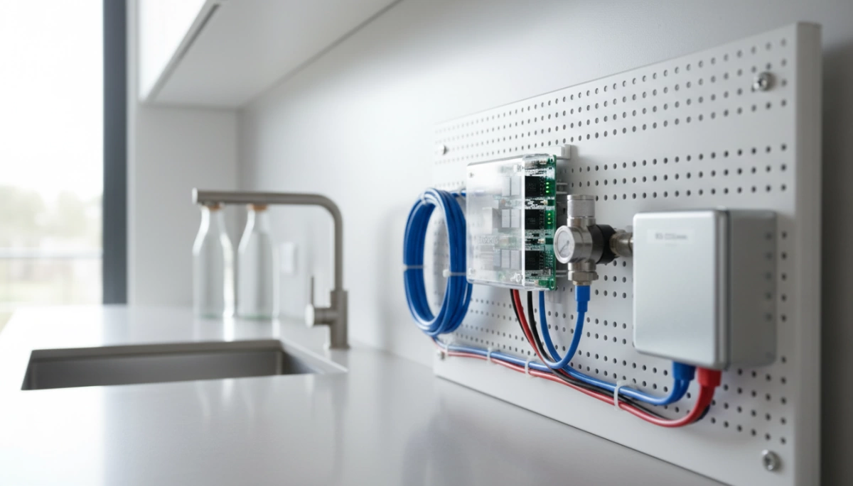
At Drip Life, we engineer our high-pressure switches around a Normally Closed (NC) Circuit logic. In the context of Reverse Osmosis (RO) systems, this means the electrical circuit remains complete—allowing current to flow to the booster pump—by default. The switch only interrupts this flow when a specific condition is met: the storage tank reaching full capacity.
This design is critical for automation. When the hydraulic pressure in the tank hits the cut-out threshold (typically 40-60 PSI), the switch physically breaks the circuit. This immediately cuts power to the pump, preventing system over-pressurization and energy waste.
The Micro-Switch Trigger Mechanism
The heart of this operation is the internal micro-switch contacts. We design these components to handle the specific demands of Inductive Load Switching. Since RO booster pumps are inductive loads, they can generate a voltage spike (arc) when the circuit is suddenly opened.
Our engineering focuses on two key mechanical actions:
- Piston Movement: As the diaphragm expands from water pressure, it pushes a central piston against the micro-switch button.
- Arc Suppression: The contacts are engineered to snap open rapidly, minimizing the duration of any electrical arc. This prevents carbon buildup on the contacts, ensuring the switch doesn’t fail in the “closed” (on) position after years of use.
Series Wiring Architecture
To ensure total system protection, the high-pressure switch is wired in series with the low-pressure switch and the pump. We utilize this architecture to create a fail-safe environment. By breaking the live line (positive wire in 24VDC systems), we ensure that the pump is completely de-energized if either safety condition is triggered.
RO Switch Logic Breakdown:
| Component | State | Circuit Status | Pump Action |
|---|---|---|---|
| High-Pressure Switch | Tank Empty (Low Pressure) | Closed (Connected) | Run |
| High-Pressure Switch | Tank Full (High Pressure) | Open (Disconnected) | Stop |
| Low-Pressure Switch | Feed Water Present | Closed (Connected) | Run |
| Low-Pressure Switch | No Feed Water | Open (Disconnected) | Stop |
This series configuration guarantees that the pump will only operate when there is sufficient feed water and the storage tank demands more production.
System Integration: The HPS and the ASO Valve
The High-Pressure Switch (HPS) functions as the electrical brain of the system, but it relies on the Automatic Shut-Off (ASO) Valve to act as the mechanical muscle. In our engineering designs, we ensure these two components operate in perfect symbiosis. While the HPS cuts the 24VDC signal to the booster pump, the ASO valve (or solenoid) physically blocks the feed water. Without this coordination, you might stop the pump but still have water running down the drain, leading to massive inefficiency.
Hydraulic Logic and Control
Effective under-sink water filter systems rely on precise hydraulic logic to manage water flow. The HPS constantly monitors RO Storage Tank Pressure. Once the tank hits the calibrated cutoff threshold (typically 40-60 PSI), the switch opens the circuit. This immediately signals the Solenoid Valve Control to close the inlet. This dual-action approach is critical for two reasons:
- Waste Reduction: It prevents continuous waste water production when the tank is full.
- System Protection: It stops the membrane from being subjected to constant line pressure.
Impact of Check Valve Failure
The check valve is often the unsung hero in this equation. It traps pressure between the membrane and the tank. If the check valve fails, that Hydraulic Back-pressure bleeds back into the membrane housing. The HPS senses this artificial pressure drop and mistakenly triggers the pump to run again. This leads to Short Cycling—where the pump pulses on and off repeatedly—which is the primary cause of premature switch failure and pump burnout. We design our circuits to be robust, but a healthy check valve is non-negotiable for stable switch performance.
Manufacturing Precision: Quality Indicators
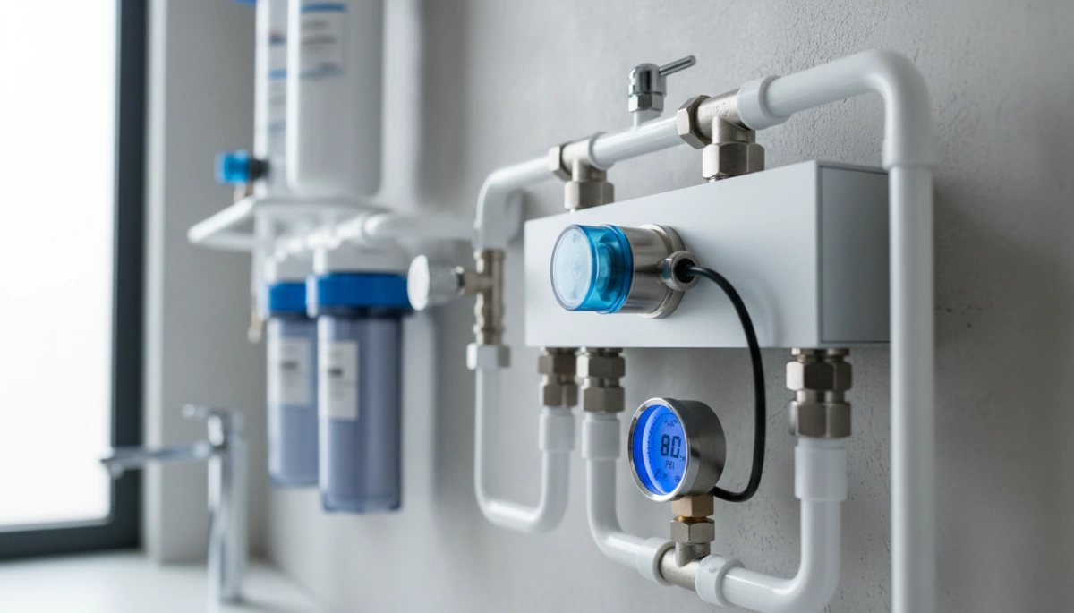
When I evaluate a high-pressure switch, I’m looking for engineering that survives the harsh, humid environment under a kitchen sink. It’s not just about turning a pump on and off; it’s about repeatability over thousands of cycles. The difference between a reliable component and a failure point often comes down to three specific manufacturing details.
- Material Fatigue and Cycle Life: The internal spring and Diaphragm Actuator take a beating every time you open the faucet. If the spring steel loses its tension or the EPDM diaphragm stiffens over time, the Cut-in and Cut-out Pressure points will drift. This mechanical drift causes erratic Pump Cycle Life, leading to short cycling that can burn out the booster pump motor.
- Contact Resistance: Since these switches often live in damp cabinets, the electrical terminals must be engineered to resist corrosion. High-quality switches use silver-plated Micro-switch Contacts to maintain low resistance. Cheap copper contacts oxidize quickly in humidity, creating heat that can weld the contacts shut during Inductive Load Switching, causing the pump to run continuously.
- Leak Prevention: While threaded ports offer robust solidity, the US market largely favors 1/4″ Quick Connect Fittings for installation speed. The engineering challenge here is ensuring the internal stainless steel collet teeth and O-rings are precise enough to hold against constant hydraulic spikes without weeping water.
Ensuring these components are top-tier is vital, especially for businesses looking at the profitability of bundling branded replacement filters with RO units, as hardware reliability directly impacts customer retention and long-term recurring revenue.
Troubleshooting via Engineering Principles
When a Reverse Osmosis system starts acting up, the high-pressure switch is often the first component blamed, but from an engineering standpoint, it is usually just reacting to issues elsewhere in the hydraulic circuit. Understanding the mechanical interaction between pressure and electrical contacts is key to accurate diagnostics.
Diagnosing Short Cycling
“Short cycling”—where the pump pulses on and off rapidly—is rarely a defect in the switch itself. Instead, it typically points to Check Valve Failure.
- The Mechanism: The check valve is supposed to hold pressure in the home reverse osmosis water filter tank. If it leaks, water flows backward, dropping the line pressure.
- The Reaction: The high-pressure switch senses this drop, engages the electrical circuit to run the pump, rebuilds pressure, and shuts off again.
- The Consequence: This rapid loop creates excessive heat and mechanical wear, drastically reducing Pump Cycle Life. If you see this behavior, check the valve before replacing the switch.
Failure to Shut Off
If the booster pump runs continuously, the switch might be failing to break the electrical circuit. This is often caused by Mineral Buildup stiffening the diaphragm, preventing it from flexing enough to trigger the micro-switch. In older units, Spring Fatigue can also occur, where the internal spring loses the tension required to counteract the hydraulic force, keeping the circuit closed even when the tank is full.
Risks of Manual Hex Screw Adjustments
Most high-pressure switches feature a small hex screw on the head, but adjusting this is risky without proper testing equipment. We calibrate these springs at our manufacturing facility to maintain a specific PSI Hysteresis (the gap between cut-in and cut-out pressure).
- Tightening too much: The pump may never reach the cut-off pressure, running until it burns out.
- Loosening too much: The system will shut off prematurely, leaving you with a half-empty storage tank.
- Best Practice: Rely on the factory calibration to ensure the safety and efficiency of the RO system.
FAQ: Engineering Insights on RO Switches
Can I adjust the pressure setting on my high-pressure switch?
Technically, yes, but proceed with caution. Most of our switches feature a small hex screw on the head that adjusts the internal spring tension. Turning this screw changes the Cut-out Pressure threshold. However, we calibrate these at the factory to shut off typically between 40 and 60 PSI to ensure optimal RO Membrane Protection. If you set the pressure too high without a gauge, the pump may never reach the cut-off point, running continuously until it overheats.
What is the difference between a high-pressure and low-pressure switch?
It comes down to where they sit in the circuit and what they protect.
- Low-Pressure Switch: Installed before the pump. It detects if the feed water supply is cut off. If there is no water, it opens the circuit to prevent the Reverse Osmosis Booster Pump from running dry and burning out.
- High-Pressure Switch: Installed after the membrane. It monitors RO Storage Tank Pressure. When the tank is full, hydraulic back-pressure triggers the switch to cut power, stopping water production. This coordination is critical in high-output units like our 600-1200GPD under sink RO system to prevent overflow and energy waste.
How do I test if my RO high-pressure switch is bad?
You can verify functionality using a multimeter. Since these switches operate on a Normally Closed (NC) Circuit, you should detect electrical continuity when there is no water pressure (switch is “on”). Once the system pressurizes, the Diaphragm Actuator pushes the piston to separate the Micro-switch Contacts, breaking the circuit. If your pump continues running even when the tank valve is closed and pressure is high, the switch has likely failed in the closed position.
Why is my RO pump pulsing on and off rapidly?
This phenomenon is known as “short cycling,” and it destroys Pump Cycle Life. It rarely means the switch itself is broken. Instead, it usually points to Check Valve Failure. If the check valve leaks, Hydraulic Back-pressure from the tank bleeds back into the membrane housing, causing the pressure to drop immediately after the pump stops. The switch senses this drop, turns the pump on for a second, pressure spikes, and it shuts off again. This rapid clicking indicates the system is losing pressure retention, not necessarily that the switch sensitivity or PSI Hysteresis is off.

