














Understanding Thermal Cross-Interference in Compact Dispensers
In a compact hot and cold water dispenser, everything happens in a tight space, so thermal cross-interference is the main enemy of efficiency. You have a hot tank, a cold tank, a compressor, and electronic controls all packed together. If the hot side “leaks” heat into the cold side, the cold system has to work harder, the hot tank reheats more often, and energy costs go up.
Thermodynamics Inside Hot and Cold Dispensers
Inside a dispenser, the thermodynamics are simple but unforgiving:
- The hot tank is constantly adding heat to keep water at a set temperature.
- The cold tank and refrigeration loop are constantly pulling heat out to keep water chilled.
- Any heat exchange between these two zones is pure energy loss and directly hurts performance.
In a good thermal isolation hot-cold dispenser, the design focuses on heat exchange reduction between these zones, so each system can operate independently and stay stable.
How Conduction, Convection, and Radiation Interfere
Thermal cross-interference comes from three main heat transfer paths:
- Conduction: Heat travels through metal brackets, shared pipes, and thin panels. Without cold bridge elimination and proper insulation engineering, the hot tank can slowly warm the cold reservoir.
- Convection: Warm air from the compressor and heating element rises and circulates around the cold tank. Poor internal water dispenser architecture and no guided airflow let this hot air pool where it does the most damage.
- Radiation: The hot tank and hot lines radiate heat toward nearby cold components, especially in compact designs without reflective or insulated barriers.
When you don’t actively control these three paths, thermal cross-interference prevention becomes almost impossible in real-world use.
Energy Waste and Performance Impact
Poor thermal isolation shows up fast on your power bill and in day-to-day performance:
- The compressor cycles more often to fight off unwanted heat, wasting power and adding noise.
- The heater runs more frequently to re-heat water that’s cooled down by nearby cold or ambient zones.
- The system struggles to hit target temperatures, so “cold” water is only cool and “hot” water isn’t hot enough during peak use.
All of this reduces your real-world energy efficiency ratio (EER) and pushes operating costs higher than they should be.
Component Fatigue and Lifespan
Thermal design choices directly affect how long your dispenser lasts:
- More cycles = more wear: When the compressor and heater have to start and stop constantly, mechanical and electrical fatigue accelerate.
- Higher operating temperatures: Electronics, seals, and plastics near hot zones degrade faster when compressor heat dissipation is not handled correctly.
- Thermodynamic instability: Unstable temperature zones cause sensors and control boards to over-correct, stressing relays, wiring, and contactors.
A dispenser with strong heat-cold separation design and stable temperature zones doesn’t just save energy; it also protects critical components and extends the practical lifespan of the entire system.
Core Principles of Thermal Isolation Design in Hot and Cold Dispensers

Smart spatial architecture and layout
In a compact hot and cold water dispenser, thermal isolation starts with smart internal architecture. I design the hot tank, cold tank, compressor, and condenser so they don’t “see” each other thermally. That means:
- Keeping the hot water path short and contained
- Keeping the cold tank away from compressor and condenser heat
- Using internal partitions and shields to cut down thermal cross-interference
This kind of water dispenser architecture is what keeps your cold water actually cold, even when the hot side is running hard.
Vertical vs. horizontal tank separation
For dual-tank thermal separation, tank positioning matters:
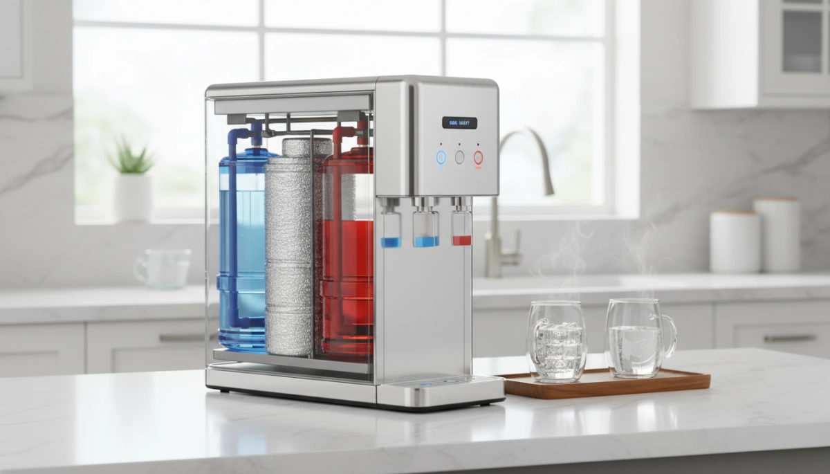
- Vertical separation: Hot tank above, cold tank below, using natural convection so heat rises away from the cold zone. This is ideal for tight floor-standing or countertop units.
- Horizontal separation: Tanks side by side with solid thermal barriers and airflow channels between them, used when height is limited.
I choose the layout based on footprint and use case, always prioritizing thermal cross-interference prevention and stable temperature zones.
Airflow channels and compressor heat
Compressor and condenser heat can easily bleed into the cold reservoir if airflow is sloppy. I design clear, controlled airflow channels so:
- Warm air from the condenser exits the rear or side of the dispenser quickly
- Cold zones are physically and thermally shielded from that hot airflow
- Fans, vents, and grilles are placed to support efficient condenser airflow management
The same mindset we use to keep RO systems ultra-quiet and efficient in our noise-optimized water filtration designs applies here: redirect heat and air where they belong.
Insulation materials and thermal barriers
Material choice is where insulation engineering really shows up:
- High-density polyurethane foam insulation around the hot and cold tanks to reduce conductive and convective heat transfer
- Vacuum insulation panels (VIP) in premium models to dramatically cut heat exchange and energy loss in the most critical surfaces
- Thermal breaks at mounting brackets, structural ribs, and external panels to avoid cold bridges that sneak heat into the cold side
By combining foam with targeted VIP, I get thermodynamic stability and strong energy loss reduction without making the unit bulky.
Thermal breaks at pipes and faucets
Pipes, faucets, and metal fittings are classic cold bridge paths if you don’t design around them. To eliminate these cold bridges, I:
- Use plastic or composite fittings where possible between hot and cold paths
- Add insulation sleeves on water lines that pass near hot components
- Isolate the heating element area from cold lines with clear thermal breaks
This kind of heat–cold separation design keeps your cold water crisp, your hot water ready, and your energy efficiency ratio (EER) where it should be over years of daily use.
Driplife’s Thermal Isolation Design in Hot and Cold Water Dispensers
At Driplife, I design our hot and cold water dispensers around strict thermal isolation so hot and cold never fight each other. We start with precision tank encapsulation, wrapping each tank with high-density polyurethane foam insulation to cut heat leaks and seal micro-gaps where thermal cross-interference usually happens. This dual-tank thermal separation keeps hot water hot and cold water cold with less energy loss.
To lock in stable temperature zones, we build independent hot and cold chambers instead of one shared cavity. Each zone gets its own sensors and dedicated control board, so the heating element and compressor don’t overcorrect or run longer than they should. That smart temperature control approach improves thermodynamic stability and directly boosts energy efficiency ratio (EER) over time.
On the back of the dispenser, we engineer rear ventilation and airflow channels to move compressor heat away from the cold reservoir. Condenser airflow management is critical: we guide warm air out and away from the cabinet so it doesn’t wash over the cold tank or piping. This heat exchange reduction lowers compressor workload, protects the cold side insulation, and keeps performance consistent in typical U.S. office, breakroom, and commercial setups. If you’re planning a system that pairs chilled dispensing with filtration, you can see the same mindset in our under-sink water chiller dispenser solutions, which are built for efficient compressor heat dissipation and long-term reliability.
ROI of Superior Thermal Isolation for B2B Buyers
When I design thermal isolation in a hot and cold water dispenser, I’m not just chasing specs—I’m chasing ROI for B2B buyers. Better thermal isolation hot cold dispenser design means less thermal cross-interference, lower power bills, and fewer service calls over the life of the machine.
Energy Efficiency, EER, And Operating Costs
Strong heat cold separation design helps the compressor run shorter, smarter cycles. With tighter insulation engineering and dual-tank thermal separation, the hot tank stays hot and the cold tank stays cold without fighting each other all day.
That directly improves the energy efficiency ratio (EER) and cuts operating costs:
- Less compressor runtime means lower kWh per month
- Smaller peak loads help with building energy management
- Better EER helps you hit internal sustainability and Energy Star–style targets
For high-traffic offices or commercial sites, that difference in EER stacks up into real dollars over a 3–5 year replacement cycle.
Stable Temperatures And Hygiene
Stable temperature zones are also a hygiene and compliance advantage. When the cold reservoir doesn’t get warmed by compressor heat or a poorly isolated hot tank, we reduce the “lukewarm zone” where bacteria can thrive.
- Consistent cold temperatures lower bacterial growth risk
- Reliable hot temperatures support better sanitation at the faucet
- Smart temperature control sensors keep both zones in their safe bands
If you already sell filtration, pairing a thermally stable dispenser with a pH balance water filter or similar treatment solution can give your customers a stronger complete-water package.
Longer Compressor And Component Life
Better thermal management architecture is one of the easiest ways to extend equipment life. When we prevent unnecessary heat exchange and improve compressor heat dissipation, every component runs under less stress:
- Compressor cycles less often, reducing wear on key mechanical parts
- Control boards and sensors stay cooler, improving electronics reliability
- Fewer extreme temperature swings reduce seal and gasket fatigue
Over time, that means fewer breakdowns, fewer warranty claims, and a longer useful life per unit.
Business Benefits For Wholesalers, Distributors, And OEMs
For wholesalers, distributors, and OEM water dispenser buyers, superior thermal cross-interference prevention turns into a business advantage:
- Stronger value story: lower total cost of ownership, not just a low purchase price
- Fewer returns and service issues tied to overheating, noise, or “not cold enough” complaints
- Better margins on premium SKUs that highlight energy loss reduction and reliability
- Stronger brand reputation when your units stay efficient and stable in real-world office environments
In short, investing in advanced thermal isolation design and heat exchange reduction pays off in lower operating costs, fewer headaches, and a more competitive product line for the U.S. market.
Sourcing Hot and Cold Water Dispensers with Strong Thermal Isolation
When I source hot and cold water dispensers, I start by looking at the thermal isolation design instead of just the price tag. Strong thermal isolation hot cold dispenser design cuts energy loss, keeps temperatures stable, and reduces service calls over the life of the unit.
How to Evaluate Internal Layout and Tank Positioning
For real thermal cross-interference prevention, the internal water dispenser architecture matters more than the brochure photos.
Look for:
- Clear dual-tank thermal separation – hot and cold tanks should be physically spaced apart, not touching, with solid insulation between them.
- Vertical vs. horizontal layout – vertical stacking can work if there’s an insulated divider and good airflow; side‑by‑side tanks need thicker insulation walls to avoid heat bleed.
- Short, insulated water paths – pipes from the hot tank should be isolated from the cold path, with thermal breaks and minimal shared metal parts.
- Heating element isolation – the heater should sit tight to the hot tank, not exposed near the cold reservoir or plastic parts.
What to Check in Insulation Type, Thickness, and Density
Not all insulation is equal, and in the U.S. power rates, small differences add up on a commercial bill.
Ask for:
- Material type – confirm it’s high‑density polyurethane foam insulation, not low‑grade or thin fiber fill.
- Thickness – continuous foam around the tank walls and top, typically 30–50 mm or more, with no big gaps or hollow “air pockets.”
- Density and coverage – consistent foam density improves thermodynamic stability; check cross‑section photos or samples if possible.
- Door, panel, and faucet areas – these are common weak spots; make sure insulation continues around them, not just on the tank body.
Why Polyurethane Foam and VIP Matter Long-Term
For long‑term performance and energy loss reduction, I focus on polyurethane foam plus, in premium models, vacuum insulation panels (VIP).
Benefits:
- Polyurethane foam insulation – great cost‑to‑performance ratio, good aging behavior, and reliable heat exchange reduction across daily hot/cold cycles.
- Vacuum insulation panels (VIP) – ultra‑low thermal conductivity; ideal for thin walls or tight cabinet spaces where we still need strong thermal cross-interference prevention.
- Cold bridge elimination – pairing foam and VIP with plastic or composite brackets avoids metal “cold bridges” that leak heat between hot and cold zones.
For customers who care about water quality as much as energy savings, I often pair these units with advanced filtration like a reverse osmosis water filter system that keeps performance consistent over time; you can see how this works in practice in our reverse osmosis water filter overview.
Key Testing Standards and Thermal Stability Reports
If I’m buying for offices, gyms, or multi‑site rollouts, I never skip the test data. Ask manufacturers for:
- Energy efficiency ratio (EER) or comparable energy rating data under standard lab conditions.
- Standby power consumption – kWh per day with steady hot and cold setpoints.
- Thermal stability reports – temperature drift over 24–72 hours at rated ambient temperature and load.
- Compressor and heater cycling logs – frequent cycling often signals weak insulation or poor compressor heat dissipation.
- Compliance certificates – UL/ETL, DOE, or equivalent U.S.‑relevant energy and safety standards.
Questions Procurement Officers Should Ask OEM Water Dispenser Suppliers
When I talk with OEM water dispenser manufacturing partners, I push hard on thermal management architecture. Strong questions make weak designs obvious fast:
- How do you physically separate hot and cold tanks, and what is the exact insulation material, thickness, and density?
- Where do you use polyurethane foam insulation vs. any VIP, and how do you ensure there are no unfilled voids around the tanks?
- What specific steps do you take for cold bridge elimination at pipes, mounting brackets, and faucets?
- How is compressor heat dissipation and condenser airflow management handled so the cold tank isn’t reheated by the back of the unit?
- What are the tested EER, standby loss, and temperature stability numbers at 77°F (25°C) room temperature?
- Can you provide exploded drawings or internal layout diagrams to verify the dual-tank thermal separation and stable temperature zones?
If a supplier can’t answer these clearly, I treat it as a red flag and move on to OEMs that take thermal isolation and long‑term operating cost seriously.