

















Are you tired of dealing with tankless countertop RO systems that fail under pressure?
High return rates due to leaks and pump burnouts are a distributor’s worst nightmare.
As an OEM manufacturer, I know that true reliability isn’t just about the filtration membrane—it’s about mastering hydraulic stability.
You might think a standard pump is enough, but without precise Water Pressure Stabilization Engineering, you are risking membrane damage and the destructive water hammer effect.
In this guide, we’re going to break down exactly how PWM booster pump technology and intelligent inlet regulation create a closed-loop pressure ecosystem within compact units.
If you want to secure high-performance products that withstand real-world fluctuations, this engineering deep dive is for you.
Let’s get technical.
The Physics of Failure: Why Unstable Pressure Destroys RO Systems
As distributors, your biggest nightmare is the “unexplained” return—the unit that leaks after a month or suddenly stops filtering effectively. We know that 90% of these failures aren’t random; they are the result of uncontrolled physics. When we design a pressure stabilization tankless RO purifier, we are fighting specific forces that degrade system integrity over time. If the inlet pressure isn’t stabilized, the hardware destroys itself from the inside out.
Membrane Stress and Microscopic Tears
The heart of the system is the most vulnerable. An RO membrane is designed for consistent osmotic pressure, not chaotic spikes. When municipal supply surges, it forces water through the membrane faster than the cross-flow can clean it. This lack of inlet pressure regulation engineering RO system leads to critical failures:
- Microscopic Tears: High-pressure spikes stretch the polyamide layer, creating micro-fissures that allow contaminants to bypass filtration.
- Accelerated Fouling: Without stable pressure, the boundary layer compacts, trapping scale and organics deep in the membrane leaves.
- Permanent Damage: Once the membrane structure is compromised, no amount of flushing can restore the rejection rate.
The Water Hammer Effect: Hydraulic Shock
You hear it as a “thump” in the pipes, but inside the machine, it’s a sledgehammer blow. When a standard solenoid valve snaps shut instantly, the kinetic energy of the moving water has nowhere to go. It transforms into a shockwave. Hydraulic shock prevention is critical here because this energy travels back through the tubing, stressing every quick-connect fitting and manifold weld. Over time, this repetitive stress causes fatigue failure in plastic components, leading to the catastrophic leaks that result in expensive property damage claims.
Inconsistent TDS Removal
Customers expect pure water, every time. However, there is a direct correlation between low feed pressure and poor performance. Reverse Osmosis requires a specific Net Driving Pressure (NDP) to overcome the natural osmotic pressure of the water.
- Low Pressure Scenario: If the pump creates insufficient pressure, diffusion takes over. Salt passage remains constant while water flux drops, resulting in high TDS product water.
- Fluctuation Issues: Without pressure surge protection countertop RO mechanisms, the TDS reading on the display will jump erratically.
- The Correlation: We treat the RO membrane rejection rate vs pressure relationship as a fixed law; if we cannot guarantee the pressure, we cannot guarantee the purity.
Engineering Solution A: Intelligent Inlet Regulation
We don’t rely on the customer’s plumbing to be perfect; we build the protection directly into the machine. In the US market, municipal water pressure fluctuation is a constant variable, with spikes often exceeding safety limits during off-peak hours. To combat this, we focus on inlet pressure regulation engineering RO system designs that actively manage the water before it ever touches the sensitive filtration membranes.
Integrated Pressure Reducing Valves (PRV)
The first line of defense in our pressure stabilization tankless RO purifier is the Integrated Pressure Reducing Valve. We don’t leave this as an external accessory; it is built into the manifold.
- Pressure Capping: The mechanism physically caps input pressure at a consistent 40-60 psi. Even if the feed water spikes to 100 psi, the internal components only see the regulated flow.
- Membrane Protection: By stabilizing the feed, we prevent the “ballooning” effect on the RO membrane, ensuring consistent pore size and rejection rates.
- Leak Prevention: High pressure is the primary cause of seal failure. Keeping the pressure within a safe range drastically reduces the stress on O-rings and quick-connect fittings.
Feed Water Solenoid Optimization
Standard solenoid valves are binary—they are either fully open or fully closed. When a standard valve snaps shut against high-velocity water, it creates a shockwave known as the water hammer effect. We utilize Feed Water Solenoid Optimization to ensure inlet solenoid valve reliability.
Our engineering approach focuses on hydraulic shock prevention through specific valve behaviors:
- Soft-Close Capabilities: Instead of an instant snap, our valves are engineered with a dampened closing action. This gradual reduction in flow dissipates kinetic energy without sending a shockwave back through the pipes.
- Cycle Durability: By reducing the physical impact during every start-stop cycle, we extend the lifespan of the solenoid itself and the surrounding tubing.
- Noise Reduction: This technology also addresses countertop water purifier pump noise reduction, as it eliminates the audible “thump” often heard in cheaper systems when the filtration cycle ends.
Engineering Solution B: PWM Booster Pump Technology
Why Standard Pumps Fail in Compact Units
In the engineering of tankless systems, space is the ultimate constraint. Traditional RO booster pumps are designed for under-sink environments where airflow is decent and size isn’t the primary concern. However, when we shrink the footprint for a countertop model, compact RO system thermal management becomes critical. Standard pumps operate on a binary basis—they are either 100% on or 100% off. Running a pump at full capacity continuously within a confined chassis generates significant heat. Without adequate dissipation, this heat degrades internal seals and electronics, leading to premature failure. Furthermore, the constant full-torque start-up creates unnecessary stress on the power supply and internal tubing.
Pulse Width Modulation (PWM) Control
To solve the heat and efficiency issues, we utilize PWM booster pump RO technology. Unlike standard pumps, a Pulse Width Modulation (PWM) pump functions much like a dimmer switch rather than a toggle switch. It allows for variable speed pump control, meaning the pump can adjust its RPMs in real-time.
Here is how the logic works inside the unit:
- Input Analysis: Sensors detect the incoming feed water pressure.
- Modulation: If the municipal pressure is high, the MCU reduces the duty cycle to the pump, slowing it down. If the pressure drops, the pump ramps up.
- Result: The membrane receives a constant, optimal pressure regardless of fluctuations from the tap.
This dynamic adjustment prevents pump cavitation protection issues and ensures the motor only uses the energy required for that specific moment, significantly reducing heat generation and extending the component’s lifespan.
Vibration Dampening Engineering
High-pressure pumps vibrate; there is no way around the physics of compressing water. However, on a kitchen counter, vibration equals noise. A rattling purifier is a non-starter for the US market, where open-plan kitchens are the standard. We address this through specialized vibration dampening engineering focused on countertop water purifier pump noise reduction.
We do not bolt the pump directly to the chassis. Instead, we utilize a floating suspension system:
- Isolation Mounts: The pump sits on industrial-grade rubber grommets that absorb high-frequency vibrations before they transfer to the outer shell.
- Flexible Connections: Rigid tubing transfers noise. We use flexible, reinforced silicone sections immediately entering and exiting the pump to break the vibration path.
- Weighted Base: The bottom of the unit is engineered with a lower center of gravity to resist resonance.
By isolating the mechanical energy, we ensure the user hears the water flowing, not the machinery working.
Engineering Solution C: The Feedback Loop (Sensors and Logic)
Hardware is only half the battle. To truly master Water Pressure Stabilization Engineering in Tankless Countertop RO Systems, we rely on a sophisticated feedback loop driven by sensors and digital logic. We do not just guess what the water is doing; we measure it constantly to ensure the system reacts faster than a pressure spike can occur. This intelligent monitoring is what separates a reliable appliance from one that leaks after six months.
High and Low-Pressure Switches
These components act as the nervous system of the purifier. They are not just passive safety features; they are active guardians of the machine’s longevity.
- Pump Cavitation Protection: If the feed water supply drops unexpectedly, a standard pump might keep spinning dry. This causes cavitation—air bubbles that implode and wreck the impeller. Our low-pressure switches cut power instantly to prevent this damage.
- System Rupture Prevention: On the flip side, a high-pressure switch RO system setup detects if internal pressure exceeds safety limits, shutting down the unit immediately to stop leaks before they start.
The Microcontroller Unit (MCU)
The MCU is the brain interpreting this data. It does not just turn things on and off; it modulates performance. When the sensors detect a fluctuation in the municipal supply, the MCU adjusts the variable speed pump control in milliseconds. This real-time modulation ensures the membrane receives a steady, consistent flow without the violent hydraulic shocks that shorten component life. Understanding the mechanics of what is an RO water filter clarifies why this precise pressure management is non-negotiable for high-efficiency filtration.
Structural Integrity: Piping and Connections in High-Pressure Zones
Integrated Waterways: The End of Spaghetti Tubing
In the past, opening a generic RO system revealed a chaotic mess of tubes and push-connect fittings. That design is a ticking time bomb for Water Pressure Stabilization Engineering in Tankless Countertop RO Systems. Every manual connection represents a potential failure point when subjected to constant pressure cycling.
We have shifted entirely to integrated waterway manifold design. Instead of individual tubes, we use a single, solid injection-molded block that contains all the necessary water channels. This drastically reduces the number of seal points. By minimizing joints and crevices, we also improve hygiene, similar to the engineering principles used to prevent mold in water filter components. This solid-state approach ensures the system handles high-pressure output without the risk of a tube popping loose inside the casing.
Burst Pressure Standards and Safety Factors
Reliability comes down to physics. If a system operates at 80 psi, designing it to withstand 90 psi isn’t enough. We adhere to strict leak-proof RO engineering standards that mandate a safety factor of at least 3x.
Our structural testing protocols include:
- Hydrostatic Burst Pressure Testing: Components are pressurized to 300+ psi to ensure the manifold structure remains intact under extreme stress.
- Fatigue Resistance: Materials must resist expansion and contraction during rapid pressure changes.
- Reinforced Sealing: All interface points use industrial-grade sealing to prevent micro-leaks.
By over-engineering the structural components, we ensure that the unit remains watertight even if municipal pressure spikes unexpectedly.
The Driplife Advantage: Our Testing Protocol
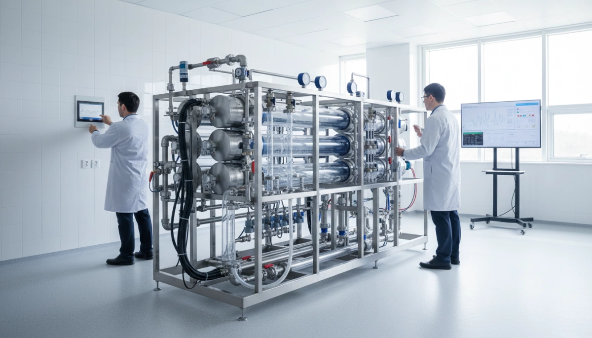
Engineering on paper is one thing; survival in a real-world American kitchen is another. At Driplife, we don’t just hope our Water Pressure Stabilization Engineering in Tankless Countertop RO Systems works—we prove it through a brutal testing regime. We understand that for a distributor, the most expensive cost isn’t the unit itself, but the logistics of a return and the damage to your brand reputation when a unit leaks. That is why our QC process is designed to break the machine in the lab so it never breaks in the customer’s home.
Water Hammer Testing: Surviving the Shock
Every time a user stops the flow of water, a shockwave ripples through the system. In a compact countertop unit, this energy has nowhere to go but into the fittings and the pump housing. To ensure hydraulic shock prevention, we subject our units to a relentless Water Hammer Test.
We run our systems through 100,000 cycles of rapid switching. This involves opening and slamming the solenoid valves shut instantly, repeatedly, to simulate years of heavy usage in a short timeframe. This process validates that our inlet solenoid valve reliability holds up against constant stress and that our tubing connections won’t fatigue and pop loose after the warranty expires. We ensure that the water hammer arrestor mechanism (whether physical or logic-based) effectively dissipates energy every single time.
Burst Testing: Pushing Limits for Safety
Standard municipal water pressure in the US can fluctuate, but we don’t design for the average; we design for the spike. Our hydrostatic burst pressure testing pushes the countertop water purifier components to limits far exceeding typical operating conditions.
- 3x Safety Factor: We pressurize the manifold and critical waterways to 3 times the normal operating pressure.
- Sustained Load: We hold high pressure for extended periods to check for micro-leaks or material creep in the plastic housing.
- Failure Analysis: We intentionally ramp up pressure until a component fails to verify that the failure point is well beyond any scenario a user would encounter.
For example, our Countertop 4-in-1 RO Cold and Hot Water Purifier with Ice Maker is built with these leak-proof RO engineering standards in mind, ensuring that even complex multi-function units maintain structural integrity under stress.
Why This Matters for Distributors
For our partners, these technical protocols translate directly into financial metrics. Pressure stability distributor selection RO purifier criteria should always prioritize testing data over theoretical specs. By rigorously validating the pressure control reliability benchmark RO purifier standards in our factory, we effectively eliminate the “infant mortality” of appliances—failures that happen in the first few months of ownership.
- Lower Warranty Claims: Robust engineering means fewer support tickets and fewer replacement units shipped.
- Brand Protection: A flooded kitchen destroys customer trust instantly. Our burst testing prevents this nightmare scenario.
- Market Confidence: You can sell these units knowing they handle the aggressive water pressure fluctuations common in high-rise apartments or older municipal grids.
We translate complex pressure surge protection countertop RO data into a simple promise: the system stays sealed, the pressure stays stable, and your profit margins stay protected.
Frequently Asked Questions About RO Pressure Stabilization
How does variable inlet pressure affect tankless RO performance?
Inconsistent pressure is the enemy of reverse osmosis efficiency. The RO membrane rejection rate vs pressure is a direct correlation; if your inlet pressure drops below the optimal range (usually caused by municipal fluctuations), the membrane cannot effectively separate dissolved solids from the water. This results in “TDS creep,” where the purity of the water temporarily degrades. Conversely, sudden high-pressure spikes can cause physical damage to components. A robust pressure stabilization tankless RO purifier ensures that regardless of what comes out of the wall pipe, the membrane receives a steady, optimized flow for consistent purity.
What is the difference between a standard pump and a PWM pump?
Think of a standard booster pump like a basic light switch—it is either 100% on or completely off. This creates sudden jolts of pressure and noise. A PWM booster pump RO system, however, functions more like a dimmer switch. It utilizes variable speed pump control to adjust the motor’s RPM in real-time based on sensor feedback.
- Standard Pump: High noise, high heat, constant wear, fixed pressure.
- PWM Pump: Soft start/stop, reduced vibration, energy-efficient, adapts to flow demand.
Why is manifold design superior to traditional tubing for pressure handling?
Traditional RO systems rely on a “spaghetti” network of flexible tubing and quick-connect fittings, creating dozens of potential failure points. An integrated waterway manifold design replaces this mess with a single, injection-molded block. By routing water through solid channels within the manifold, we eliminate the risk of tubing popping off during pressure surges. This structural rigidity is essential for passing high-stress benchmarks and maintaining the reliability expected of a high-quality, NSF certified water filter system.