














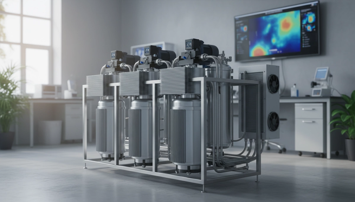
You might already know that high-output RO units are dominating the modern water treatment market…
But there is a silent killer inside those sleek, compact cases: Heat.
As a manufacturer, I know that pushing 600 to 1000 GPD generates massive thermal energy. If that heat gets trapped, your pump fails, your electronics fry, and your customer satisfaction plummets.
In this post, you’re going to learn the engineering secrets behind effective heat dissipation design.
We’ll cover everything from active cooling systems to airflow dynamics that ensure continuous, heavy-duty operation without the risk of thermal tripping.
If you are looking to source equipment that prioritizes reliability over shortcuts, this guide is for you.
Let’s dive in.
The Thermodynamics of RO: Where Does the Heat Come From?
When we engineer high-performance systems like our G3 800 GPD series, we aren’t just managing water flow; we are managing energy. A common concern for homeowners upgrading to tankless systems is the operating temperature of the unit. To understand Heat Dissipation Design in High Output RO Units, we first need to identify exactly where that thermal energy originates inside the chassis. It isn’t random; it is a direct result of the physics required to purify water at high speeds.
Booster Pump Friction and Motor Load
The heart of any high-GPD RO thermal management strategy is the booster pump. To deliver a cup of clean water in just 6 seconds—a hallmark of our G3 model—the internal pump must generate significant pressure to force water through the ultra-dense 0.0001-micron RO membrane.
- Mechanical Friction: The rapid rotation of pump bearings and diaphragms creates friction heat.
- Electrical Load: Drawing power to maintain high PSI for 800 GPD output converts a portion of electrical energy into waste heat.
- Continuous Duty: Unlike slower systems that rest often, high-demand usage keeps the motor hot, requiring robust RO booster pump overheating solutions.
Electronic Components and PCB Heat Generation
Modern filtration isn’t just mechanical; it’s digital. Our units incorporate smart faucets, real-time TDS monitoring, and auto-flush protocols. These features rely on a Printed Circuit Board (PCB) and power transformers that convert standard 110V-240V outlets into usable low-voltage power.
- Voltage Conversion: Stepping down voltage generates steady thermal radiation.
- Smart Sensors: Continuous monitoring chips contribute to the overall thermal load.
- Component Density: Electronic component cooling in RO becomes critical as we pack more technology into smaller footprints.
The “Heat Trap” Effect in Compact Designs
One of our biggest selling points is the tankless design, which saves up to 70% of under-sink space. However, this compact architecture presents a unique engineering challenge known as the “Heat Trap.”
- Reduced Air Volume: With less empty space inside the case, hot air stagnates rather than circulating.
- Insulation: Sound-dampening materials used to keep the unit quiet can inadvertently insulate the motor, trapping heat inside.
- Thermal Saturation: Without active tankless RO heat dissipation strategies, the internal ambient temperature rises quickly, potentially stressing the system during long fill cycles.
Critical Impacts of Overheating on System Performance
When we engineer high-output systems like our G3 800 GPD model, managing the thermal load is just as important as the filtration speed. If heat isn’t dissipated effectively, it creates a domino effect that compromises the entire unit. The most immediate risk is motor thermal trip prevention. The high-pressure booster pumps required to drive water through a 0.0001-micron RO membrane generate significant energy. Without proper heat management, the motor’s internal safety breaker trips, causing unexpected system shutdowns to prevent catastrophic failure. This is why our units feature built-in over-work protection—to monitor these levels and ensure the pump doesn’t push past its thermal limits during heavy usage.
Membrane Flux and Temperature Sensitivity
Heat doesn’t just stop the motor; it alters the chemistry of filtration. TFC membrane temperature limits are a real constraint in reverse osmosis. If the internal temperature creates a “heat trap” inside the compact under-sink chassis, it can affect the membrane’s flux (flow rate) and rejection rate.
- Rejection Stability: Excessive heat can temporarily expand membrane pores, potentially allowing higher TDS levels to pass through.
- Structural Integrity: Chronic overheating degrades the composite material of the RO filter, shortening its lifespan significantly below the rated 24 months.
Understanding how a water filter works at a microscopic level highlights why thermal stability is non-negotiable. We rely on consistent pressure and temperature to maintain that 2:1 pure-to-drain ratio.
Component Lifespan and Thermal Degradation
Long-term RO system longevity engineering depends on keeping the electronics cool. Our tankless systems are packed with smart technology, from real-time TDS monitoring sensors to the main control PCB. Heat is the enemy of these electronic components. Continuous exposure to high temperatures accelerates thermal degradation, leading to sensor drift or board failure. By utilizing an Integrated Waterway design, we reduce the clutter of internal tubing, allowing for better thermal regulation and preventing the buildup of hot pockets that could damage the smart faucet connections or the power supply unit.
Advanced Heat Dissipation Strategies
When we engineer high-output units like our G3 (800 GPD) and G2 (600 GPD) models, managing the thermal load is just as critical as the filtration accuracy. In the world of tankless RO heat dissipation, relying solely on basic passive cooling—like simple metal heat sinks—often isn’t enough for continuous duty cycles. We have to implement smarter, more aggressive strategies to keep the booster pump and electronics within safe operating limits.
Active vs. Passive Cooling Differences
Understanding the distinction between cooling methods is vital for selecting a system that lasts. Passive cooling relies on natural convection and materials to absorb heat, while active cooling technology for water filters involves dynamic elements to move heat away from critical components.
| Feature | Passive Cooling | Active Cooling / Smart Management |
|---|---|---|
| Mechanism | Metal fins, chassis conduction | Integrated fluid dynamics, electronic sensors |
| Energy Usage | None | Minimal (part of system operation) |
| Efficiency | Low (struggles with high GPD) | High (adapts to load) |
| Application | Standard low-flow units | Industrial-grade RO cooling systems & High-GPD units |
The “Double Cooling” Architecture Explained
Our approach to high-GPD RO thermal management utilizes a “Double Cooling” architecture. First, we leverage the Integrated Waterway. This isn’t just for preventing leaks; the solid integrated board acts as a massive thermal mass. Since cold water is constantly flowing through these channels during operation, it naturally absorbs waste heat generated by the adjacent pump motor. This effectively turns the water flow itself into a coolant, stabilizing the temperature of the internal components.
Second, we incorporate intelligent electronic monitoring. The system features over-work protection, which actively monitors the operational state. If the unit runs continuously beyond a safe threshold (risking heat buildup), the system intervenes to prevent the motor from reaching a thermal trip point. This ensures the RO booster pump overheating solutions are proactive rather than reactive.
Airflow Dynamics and Internal Wind Tunnels
In compact, tankless designs, trapping heat is a major risk. To combat this, the internal chassis layout is engineered to facilitate compact RO internal airflow. By optimizing the placement of the pump, power supply, and filters, we create natural “internal wind tunnels” that allow hot air to rise and escape through designated vents rather than recirculating around sensitive electronics.
Achieving this level of thermal efficiency requires exact manufacturing standards. The precision engineering in RO housing ensures that every component fits perfectly, leaving the calculated air gaps necessary for convection cooling without wasting space. This meticulous design prevents the “heat trap” effect common in lesser tankless units, ensuring consistent performance even during high-demand usage.
Material Science in Thermal Management
When designing high-performance systems like our G3 800 GPD model, choosing the right materials is just as critical as the filtration rating. You cannot pack a powerful booster pump into a compact chassis without addressing component protection RO protocols. We focus on materials that naturally aid in heat transfer rather than trapping it inside the unit.
Aluminum and Copper Heat Sinks
In the world of electronics cooling RO systems, metals like aluminum and copper are the heavy lifters. For the motor assemblies in high-output units, we rely on the high thermal conductivity of these alloys to act as passive heat sinks. They rapidly draw thermal energy away from the pump head and motor windings, preventing the “thermal throttling” that causes inconsistent water flow. This approach ensures that the heart of the system remains cool, even when you are filling multiple pitchers back-to-back.
Thermal Interface Materials (TIMs)
Even the best heat sink fails if there is an air gap between it and the heat source. We utilize advanced Thermal Interface Materials (TIMs) to bridge these microscopic gaps. This ensures that the heat generated by the PCB and pump transfers efficiently to the dissipation structures, maintaining thermal efficiency RO standards throughout the machine’s lifespan.
Chassis Ventilation and Dust Prevention
A reverse osmosis water filter under sink often lives in a dusty, enclosed cabinet. Our design philosophy balances airflow with protection:
- Strategic Venting: The chassis includes designated intake and exhaust zones to encourage natural convection, keeping the internal temperature stable.
- Dust Mitigation: We design the housing to minimize dust ingress, which acts as a thermal insulator and can lead to overheating over time.
- Compact Integration: By using our signature integrated waterway, we reduce internal clutter, improving airflow paths around critical electronic components.
Continuous Duty Reverse Osmosis System Performance
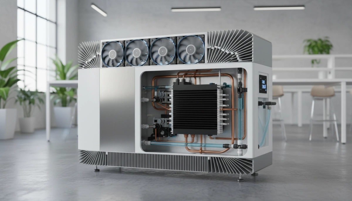
When evaluating heat dissipation RO design, we have to look at how the unit behaves under different stress loads. In a typical US household, an RO system operates intermittently—filling a glass of water takes about 6 seconds with our G3 800 GPD model. In these short bursts, heat generation is negligible. However, the real engineering challenge arises during continuous operation, such as filling large stockpots or pitchers, where the internal components face sustained thermal stress.
Residential vs. Commercial Load Stress Tests
While our units are designed for residential elegance, the internal engineering must withstand near-commercial demands to ensure long run reliability RO. A standard residential pump might overheat and trigger a thermal shutdown after 10 minutes of continuous running. High-output systems require a more robust approach to prevent thermal throttling in water treatment.
We utilize a “stress test” protocol to ensure stability:
- Intermittent Mode: Simulates daily usage (20-30 short activations). The system relies on passive cooling through the chassis.
- Continuous Mode: Simulates a 30-minute run time. Here, the integrated waterway acts as a crucial thermal buffer, helping to distribute the heat generated by the booster pump away from sensitive electronics.
Stability Metrics and Performance Curves
Heat is the enemy of consistency. As the temperature of the pump motor rises, efficiency can drop, potentially affecting the flow rate and the rejection rate of the membrane. To combat this, our G-series models (G2 and G3) incorporate over-work protection sensors. These sensors monitor the operational status to prevent the system from reaching critical temperatures that could damage the 0.0001-micron membrane.
Performance stability under heat load:
| Metric | Cold Start (First 30 Seconds) | Continuous Load (After 15 Minutes) |
|---|---|---|
| Pump Temperature | Ambient | Stabilized (via Integrated Waterway) |
| Flow Rate | 100% Output (0.55 gal/min) | >95% Output Consistency |
| TDS Rejection | Peak Efficiency | Stable (No thermal degradation) |
By managing these thermal loads effectively, we ensure that the system maintains precise filtration, preserving the strict micron ratings explained for multistage RO even during heavy usage. This attention to thermal dynamics is what separates a standard under-sink filter from a high-performance continuous duty reverse osmosis system.
What to Look for When Sourcing High-Output RO Systems
When you are in the market for a continuous duty reverse osmosis system, you have to look past the flashy GPD numbers on the box. The real test of a machine is how it handles the stress of daily, high-volume use without burning out. As a supplier, we see too many units fail because the high-GPD RO thermal management wasn’t prioritized during the design phase. You need a system that balances raw power with intelligent engineering to ensure long run reliability RO.
Checklist for Buyers: Fans and Duty Cycles
If you are sourcing units for residential or light commercial resale, use this checklist to weed out the poorly designed models. A robust heat dissipation RO design is non-negotiable for 600+ GPD systems.
- Duty Cycle Ratings: Check the manufacturer’s specs for continuous runtime limits. A quality unit should handle long fills without triggering a motor thermal trip.
- Smart Protection: Does the system have built-in over-work protection? This feature is critical for preventing thermal throttling in water treatment components.
- Internal Layout: Look for spacing around the pump. Tightly packed units without directed airflow often suffer from the “heat trap” effect.
- Efficiency Ratios: Systems with poor drain ratios work the pump harder for less product water. High-efficiency designs (like 2:1) generate less heat per gallon produced.
The Driplife Advantage in Thermal Engineering
At Driplife, we don’t just rely on slapping a fan on a motor; we engineer the heat out of the equation from the start. Our flagship G3 and G2 models utilize an advanced Integrated Waterway design. By replacing complex internal tubing with a solid integrated board, we drastically reduce flow resistance. Less resistance means the booster pump doesn’t have to work as hard to push water through the 0.0001-micron membrane, resulting in significantly lower operating temperatures and better component protection RO.
We also prioritize intelligent monitoring. Our systems come equipped with smart sensors that provide real-time over-work protection. If the unit detects extended continuous operation that could risk overheating, it manages the cycle automatically to protect the core electronics. This ensures that the system maintains the precision required to remove contaminants—ensuring your water is safe enough that you don’t have to wonder do water filters filter out fluoride effectively. With Driplife, you get a system designed for longevity, safety, and consistent performance.
Frequently Asked Questions About RO Heat Management
Why do high-GPD RO systems tend to overheat?
High-output units, specifically those pushing 800 GPD or more, require powerful internal booster pumps to force water through the ultra-dense 0.0001-micron RO membrane. This process generates significant kinetic energy and motor heat. In compact, tankless designs, components are packed tightly to save under-sink space. Without proper High-GPD RO thermal management, this heat gets trapped. Our systems utilize an integrated waterway design that helps distribute thermal loads more effectively than traditional tubing messes, preventing the “heat trap” effect common in lesser engineered units.
What is the safe operating temperature for TFC membranes?
TFC membrane temperature limits generally cap out around 113°F (45°C), though optimal performance occurs at lower, stable temperatures. If the internal environment exceeds these limits due to pump heat, the membrane pores can expand, reducing the system’s ability to filter out contaminants. Maintaining thermal stability is essential to ensure your system continues to eliminate the chemical taste of city water effectively. We engineer our G3 and G2 series with over-work protection sensors that monitor operation, ensuring the unit stays within a safe thermal range to protect the membrane’s structural integrity.
How does active cooling extend pump life?
Heat is the primary enemy of electric motors and printed circuit boards (PCBs). RO booster pump overheating solutions, such as intelligent duty cycles and heat-dissipating chassis designs, prevent the motor windings from degrading. When a pump runs cool, it maintains consistent pressure without drawing excess amperage. This thermal efficiency directly translates to longevity, ensuring your system delivers that fast 6-second cup fill rate for years rather than burning out after a season of heavy use.